by a distance of two to three times the spacing between the parallel stub conductors.
#J POLE GAIN FREE#
The parallel conductors must be kept free of moisture, snow, ice and should be kept away from other conductors including downspouts, metal window frames, flashing, etc. The quarter wave parallel transmission line stub has an external electromagnetic field with strength and size proportional to the spacing between the parallel conductors. Like all antennas, the J-pole is sensitive to electrically conductive objects in its induction fields (aka reactive near-field region ) and should maintain sufficient separation to minimize these near field interactions as part of typical system installation considerations. The net effect of the perturbation caused by quarter-wave stub is an H-plane approximate gain from 1.5 to 2.6 dBi (-0.6 dBd to 0.5 dBd). The pattern in the elevation or ( E plane) reveals a slight elevation of the pattern in the direction of the J element while the pattern opposite the J element is mostly broadside. The slight increase over a dipole's 2.15 dBi (0 dBd) gain represents the small contribution to the pattern made by the current imbalance on the matching section.

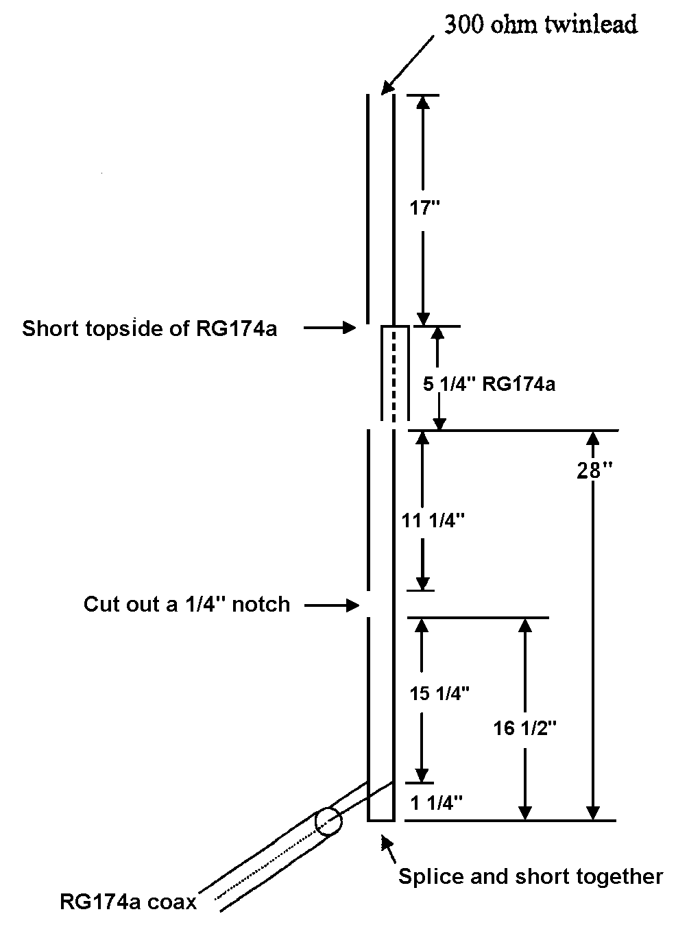
At right angles to the J-stub, the gain is closer to the overall average: about 2.2 dBi (0.1 dBd). Measurements and simulation confirm the quarter-wave stub modifies the circular H-plane pattern shape increasing the gain slightly on the side of the J stub element and reducing the gain slightly on the side opposite the J stub element. Primarily a dipole, the J-pole antenna exhibits a mostly omnidirectional pattern in the horizontal (H) plane with an average free-space gain near 2.2 dBi (0.1 dBd). Being a half-wave antenna, it provides a small gain over a quarter-wave ground-plane antenna. During construction the proper attachment point for the feed-line is found by sliding the connection of the feedline back and forth along the stub while monitoring the SWR until an impedance match is obtained. By attaching the antenna's feedline to the proper point along the transmission line, the stub will transform this impedance down to match the lower feedline impedance, allowing the antenna to be fed power efficiently. A shorted quarter-wave stub has a similar high impedance node at its open end, making a good match to the antenna. A half-wave antenna fed at one end has a current node at its feedpoint, giving it a very high input impedance of 800 - 2000 ohms. The J-pole antenna is an end-fed omnidirectional half-wave antenna that is matched to the feedline by a quarter wave parallel transmission line stub (Lecher line). When the radiating half-wave section is mounted horizontally, at right-angles to the quarter-wave matching stub, the variation is usually called a Zepp antenna. By 1936 this antenna began to be used for land-based transmitters with the radiating element and the matching section mounted vertically, giving it the shape of the letter "J", and was named the J antenna by 1943. Trailed behind the airship, it consisted of a single element, one half wavelength long radiator with a quarter wave parallel transmission line tuning stub which matches the antenna to the feedline. It was invented by Hans Beggerow in 1909 for use in Zeppelin airships. The J-pole antenna, more properly known as the J antenna, is a vertical omnidirectional transmitting antenna used in the shortwave frequency bands.


 0 kommentar(er)
